How To Measure Laser Beam Quality With M2 Measurement


M² measurement is a standardized method for quantifying the quality of a laser beam. It compares the actual beam to an ideal Gaussian beam, where M² = 1 represents a perfect Gaussian profile. ISO 11146 standard defines how to measure the beam width, divergence, and M² beam quality factor of laser beams. According to ISO 11146, the procedure involves preparing the laser beam, focusing it with appropriate optics, and measuring its radius at multiple positions along the propagation axis. These measurements are then fitted to mathematical models to determine the beam waist, Rayleigh length, and ultimately the M² value. From the beam radius (as a function of propagation distance) and the waist location, the M² value can be calculated. This value indicates the relative beam quality and the laser's ability to be focused.
The following steps outline the recommended procedure for performing an M² measurement:
1. Start With a Collimated Beam
For an accurate M² measurement, it is essential to begin with a well-collimated beam. Collimation ensures the laser rays are parallel before entering the focusing optics, minimizing errors in subsequent measurements. A collimating device—typically a lens or a collimator assembly designed for the laser’s divergence and wavelength—is used to align the rays into a parallel beam. Fiber-coupled sources often use collimation packages, while free-space lasers may require adjustable collimating lenses.
2. Use an Aberration-Free Lens To Focus the Laser Beam
The next step is to focus the collimated beam with a lens of known focal length. The lens should be as close to aberration-free as possible, meaning it should not introduce distortions such as spherical aberration, astigmatism, or surface imperfections. Optical-grade lenses with high-quality coatings are recommended, as any aberrations would distort the beam waist and compromise the accuracy of the M² calculation.
3. Measure the Diameter of the Beam at Various Positions Around the Focal Point
The beam waist is the minimum radius of the beam. This will be the radius of the beam at the focal point of the laser. However, due to inaccuracies in field measurements, it is not possible to precisely measure this beam waist at a single point. Instead, according to ISO 11146 for testing laser beams, it is necessary to take multiple measurements around the known focal point and find the minimum of these measurements to establish the beam waist.
At least 10 data points of beam radius should be taken. About half of these points should be taken close to the focal point (within one Rayleigh length of the focal point), and the other half should be taken further away from the focal point (more than two Rayleigh lengths away). These measurements will be of the laser beam width in both the x direction and the y direction (as the beam may not be perfectly circular).
4. Use the Regression Equations Detailed in the ISO Norm to Fit a Hyperbola to Your Data Points for Both the X and Y Axis
The reason for taking data points at different distances from the laser beam focal point is to fit a hyperbola closely to the plotted data. The ISO norm specifies the regression equations to be used for fitting this hyperbola. The data points should be plotted showing the beam radius against the distance from the lens. The hyperbola will show the minimum beam radius, and therefore give the beam waist. A hyperbola should be plotted for both the x-direction and the y-direction.
5. Extract the Values for, w0, zR, and M2 for Each Axis
Using the hyperbola fitted to your data points, the minimum beam radius is easily shown as the beam waist (w0). The Rayleigh length (zR) can be calculated as the distance at which the laser radius is greater than the beam waist by a factor of the square root of 2. For a circular beam, this is the distance at which the cross-sectional area is twice the minimum at the beam waist. These values can be determined for a laser beam in both the x-direction and the y-direction.
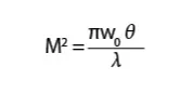
Finally, with the beam waist known, the M2 factor can be determined by calculation. It is calculated by using the following equation:
M2 factor calculation.
Why Is It Important To Understand Laser Beam Quality?
It is essential to understand laser beam quality because it affects the quality of the cut the laser produces. Laser beam quality is a measure of how precisely the laser can be focused—a low-quality laser will not be focused into a small, intense point, but rather be more widely distributed. This will give a lower intensity at the cutting point and create a wider cut. For more information, see our guide on Laser Beam Quality.
What Is the M2 Factor?
The M2 factor is also known as the beam quality factor or the beam propagation factor. It is a measure of how closely a laser beam resembles a Gaussian beam. The ideal Gaussian beam is brightest in the center, and its intensity follows a normal distribution in each direction away from the center.
The M2 factor is calculated by the measurement of a laser’s beam waist, which is the width of the beam at its narrowest point. This is determined by measuring the beam radius at various distances around the focal point. Once the beam waist w0 is known, the M2 factor is calculated by the following formula:
M2 factor calculation.
How Important Is the M2 Factor for Laser Beam Quality?
The M2 factor is important for laser beam quality. It is a common, well-defined (as specified by ISO 11146) means of communicating how close the measured beam is to ideal. The M2 factor is essential because it provides information on how precisely a beam can be focused and its effectiveness in applications such as laser cutting.
However, other parameters can provide further information about beam quality (such as Power in a Bucket or the Strehl ratio), so M2 measurement is not the only way to communicate laser beam quality.
"M² measurement quantifies the divergence between an actual laser beam and its theoretical Gaussian model, offering a precise diagnostic of beam propagation characteristics. It highlights that even well-designed optical systems exhibit deviations due to alignment tolerances, lens aberrations, and thermal lensing effects. Rather than treating these as flaws, M² analysis reframes them as measurable parameters that define focusability and spatial coherence. The process takes beam quality from theory to measurement, converting abstract optical principles into concrete, quantifiable parameters. In high-precision systems, this transition is essential for diagnosing performance limits and guiding practical optimization."
ISO 11146 Rules for Measuring the Laser Beam Diameter
The M² beam quality factor is standardized by ISO 11146, which specifies how to measure beam widths, divergence, and beam propagation. To ensure accurate and repeatable results, the standard defines several requirements for beam diameter measurements. These rules are critical when using CCD or CMOS cameras as beam profiling sensors:
- The sensor’s field of view must cover at least three times the expected beam diameter to ensure that the entire beam, including the outer regions defined by the second-moment method, is fully captured.
- The beam must be resolved with at least 10 pixels across its diameter. If the beam appears smaller than 10 pixels, a sensor with finer pixel resolution or magnifying optics should be used to avoid undersampling errors.
- The beam diameter must be defined using the D4σ (second-moment) method, which corresponds to four times the standard deviation of the intensity distribution. This standardized definition provides consistency even for non-ideal or asymmetric beams.
- Background light and electronic noise should be eliminated by shielding the sensor from stray light and applying background subtraction to isolate the accurate beam signal.
What Are the Types of Equipment To Measure Laser Beam Quality?
The types of equipment to measure laser beam quality are:
1. Lens
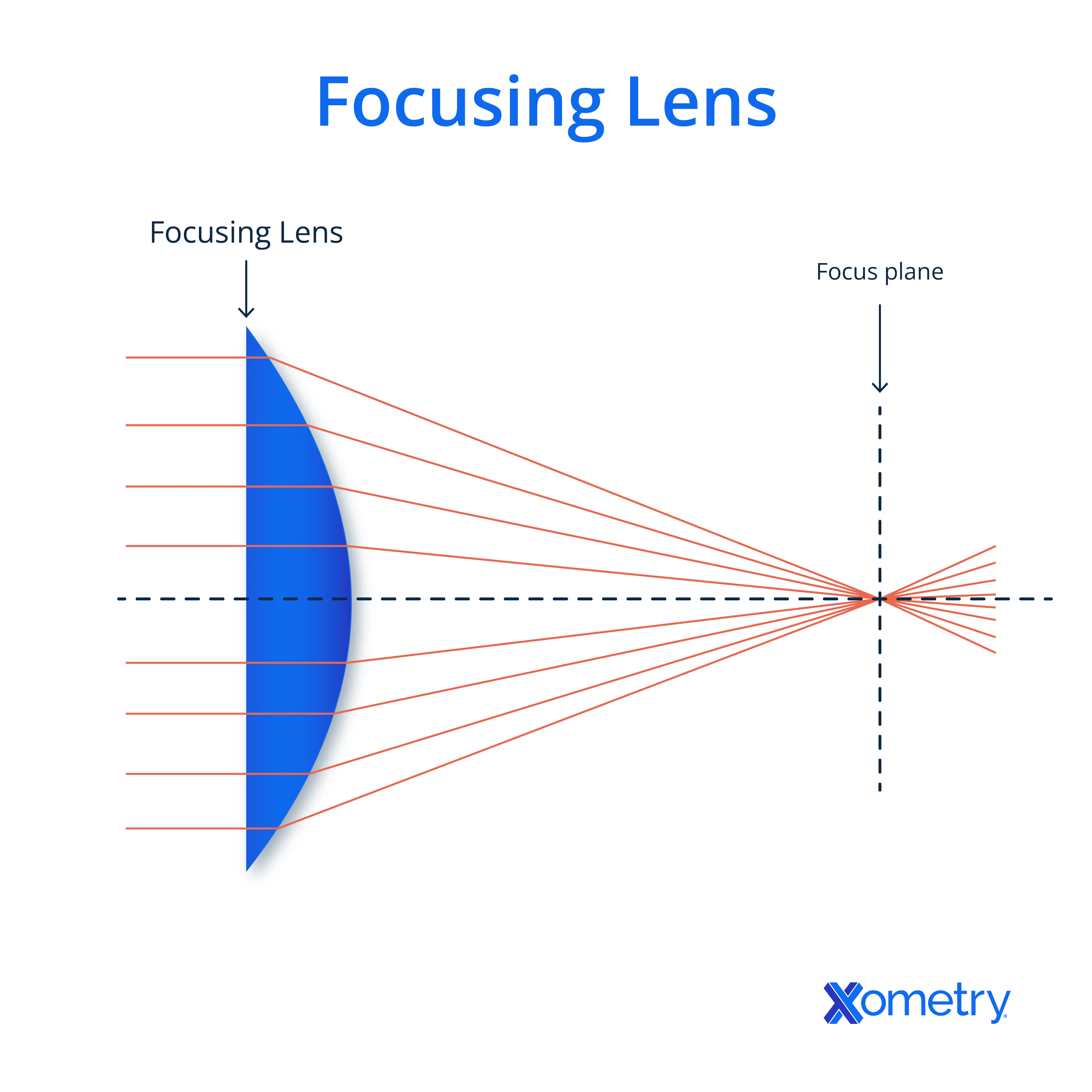
A focusing lens of known focal length and minimal aberration is used to bring the collimated laser beam to a waist. This allows the beam radius to be measured at defined positions along the propagation axis. The lens properties (focal length, coatings, and optical quality) must be well characterized to ensure accurate M² determination.
2. Beam Profiler
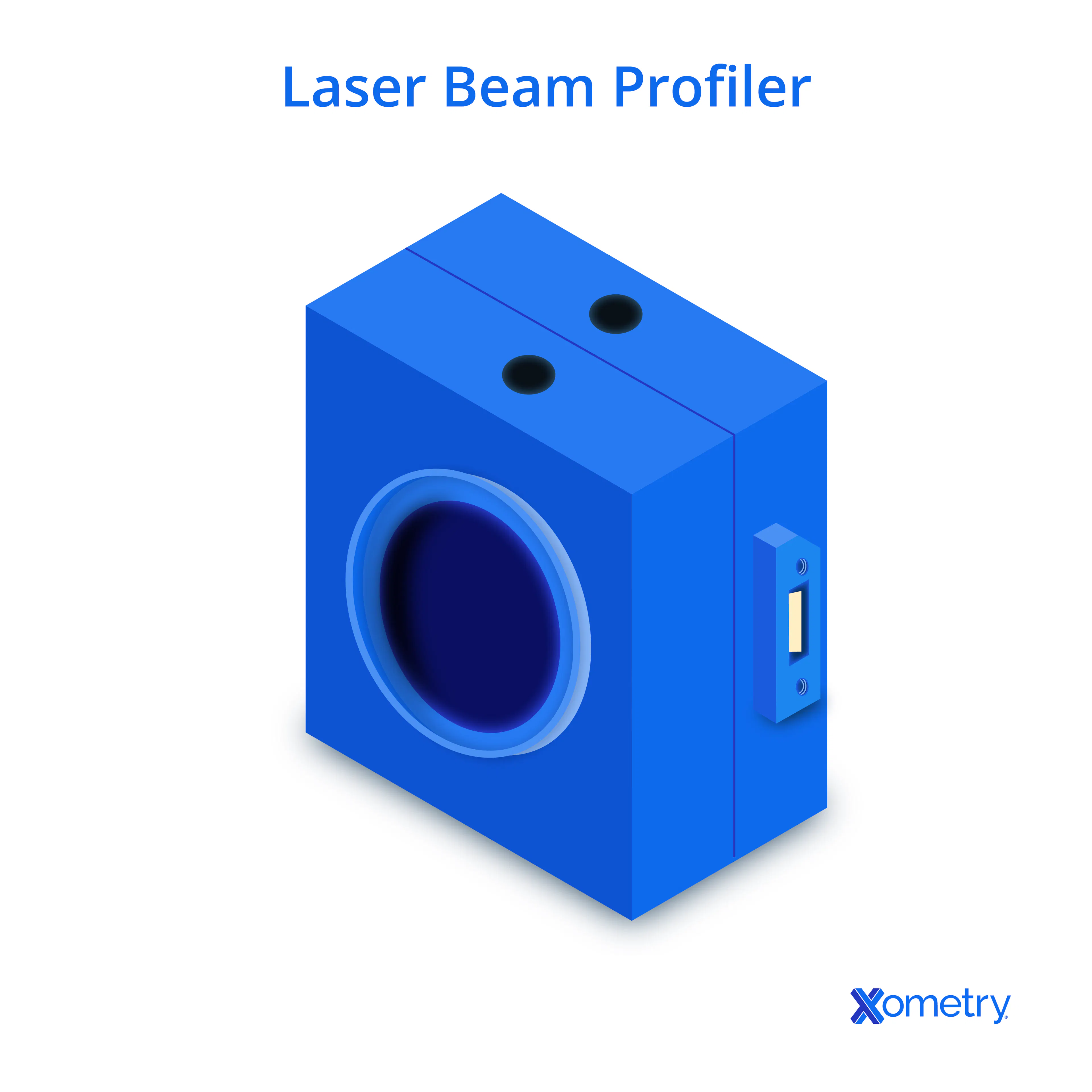
A beam profiler—typically a CCD or CMOS camera with appropriate attenuation optics—is the primary device for measuring the beam diameter. It is positioned at multiple axial locations around the beam waist to collect diameter data for M² calculation. The profiler should meet ISO 11146 requirements, including sufficient resolution (≥10 pixels across the beam) and field of view (≥3× beam diameter).

3. Ruler or Translation Stage
A ruler or, more commonly, a translation stage with a position scale, is used to place the sensor at precise distances along the optical axis. This allows multiple diameter measurements to be taken before and after the focal point, as required by ISO 11146. For higher precision, motorized translation stages are often preferred over manual rulers.
Frequently Asked Questions About Measuring Laser Beam Quality with M2 Measurement
Summary
This article presented measuring a laser beam quality with M2 measurement, explained what they are, and discussed the various steps and calculations involved. To learn more about measuring a laser beam quality, contact a Xometry representative.
Xometry provides a wide range of manufacturing capabilities, including sheet cutting and other value-added services for all of your prototyping and production needs. Visit our website to learn more or to request a free, no-obligation quote.
Disclaimer
The content appearing on this webpage is for informational purposes only. Xometry makes no representation or warranty of any kind, be it expressed or implied, as to the accuracy, completeness, or validity of the information. Any performance parameters, geometric tolerances, specific design features, quality and types of materials, or processes should not be inferred to represent what will be delivered by third-party suppliers or manufacturers through Xometry’s network. Buyers seeking quotes for parts are responsible for defining the specific requirements for those parts. Please refer to our terms and conditions for more information.