Designing Normalized Coped Cuts on Round Tube

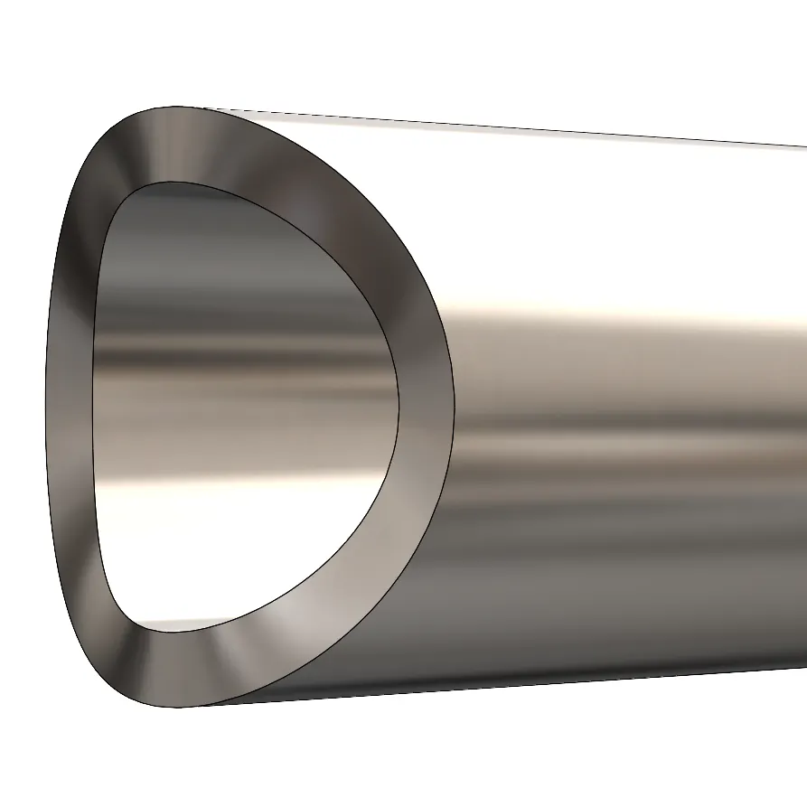
Xometry instantly quotes laser tube cutting and tube bending projects through our Instant Quoting Engine. Quoted projects will always assume normal to surface cuts which reduces lead time and price. To learn more about what normal to surface cuts are and why they are industry standard, click here.
Normalizing your tube cuts may seem daunting, but it only takes a few tools! This article will explain how to normalize cuts in SolidWorks using two methods. These methods will normalize copes, holes, and most other cuts.
Note that these methods will not correctly normalize miter cuts. To learn how to do this, review Designing Normalized Mitered Cuts on Round Tube.
Replace Face Method
This method is a reliable way to normalize cuts on round tubing and only requires three tools. It involves replacing faces with a ruled surface.
1. Make a Ruled Surface
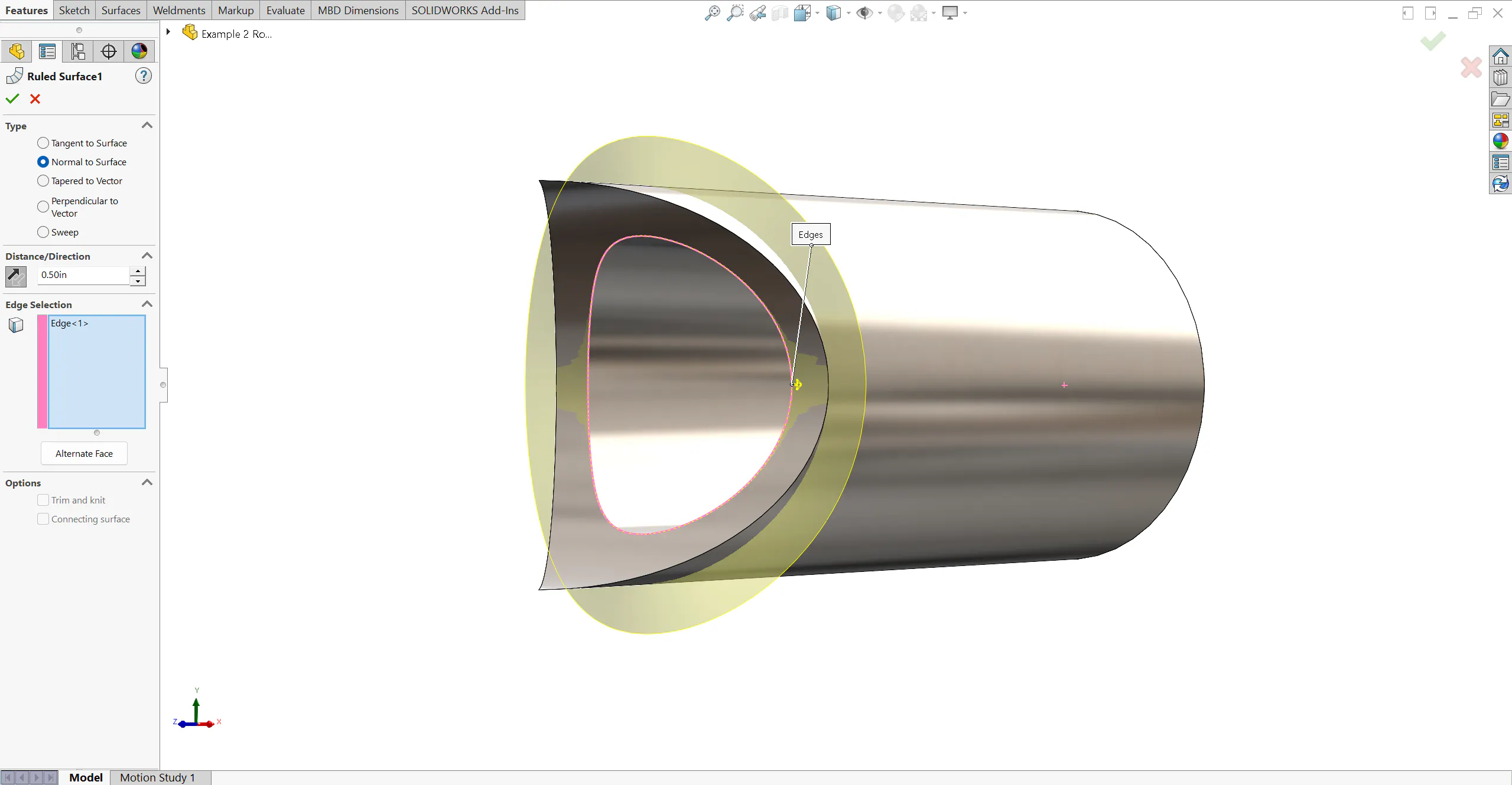
Start by clicking the Ruled Surface tool from the Surfaces tab. Before selecting anything, set the “Type” to “Normal to Surface”. This will make the ruled surface extrude normal to the surface of the tube.
Next, select the inside edge of your cut feature. This selection will be recorded as the “Edge Selection“. A yellow preview of your ruled surface should appear.
Then, input a distance greater than the thickness of your tube. The ruled surface should extrude past the outside surface of the tube. You may need to click the “Reverse Direction” icon to change the direction of your ruled surface.
Finally, click OK.
Pro Tip: If the ruled surface is not extruding outward, select your edge from the Edge Selection and click “Alternate Face”. This will alternate the face the tool is referencing.
2. Use the Replace Face Tool
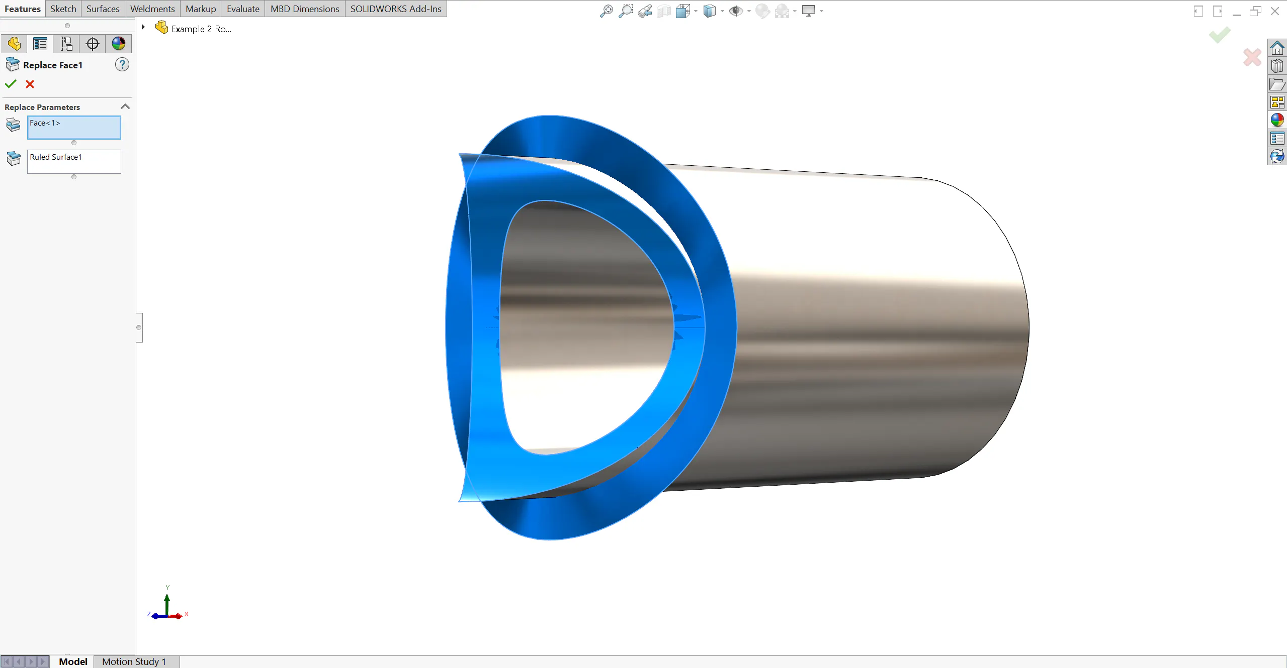
Now that you have your ruled surface, click the Replace Face tool in the Surfaces tab.
Start by selecting the “Target Faces for Replacement”. If there are multiple target faces, make sure to remember the order you select them in.
Next, select your ruled surface as the “Replacement Surface”. If your ruled surface has multiple faces, be sure to select them in the same order you selected the target faces. Every target face should have a corresponding replacement face located such that the replacement does not create self-intersecting geometry. Otherwise, your feature will receive an error.
The ruled surface may be automatically selected. If the feature results in an error, right click the “Replacement Surfaces” and click “Clear Selections”. Then manually select the “Replacement Surfaces”.
Finally, click OK.
Pro Tip: In rare situations, the number of “Target Faces for Replacement” will not equal the number of “Replacement Surfaces”. To fix this, use the Knit Surface tool from the Surfaces tab to knit faces of your ruled surfaces together until every target face has a corresponding replacement surface.
3. Delete the Surface Bodies
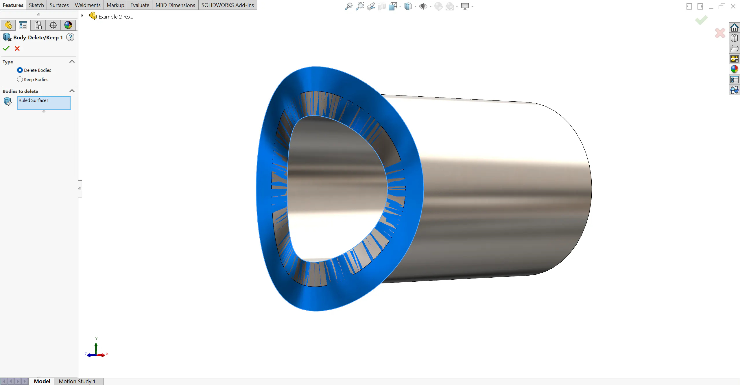
To remove your ruled surface, click on the Surface Bodies dropdown in the FeatureManager and select the surfaces making up the ruled surface.
Next, right click and select the Delete/Keep Body tool. Change the “Type” from “Keep Bodies” to “Delete Bodies” and click OK. Your ruled surface should now be deleted.
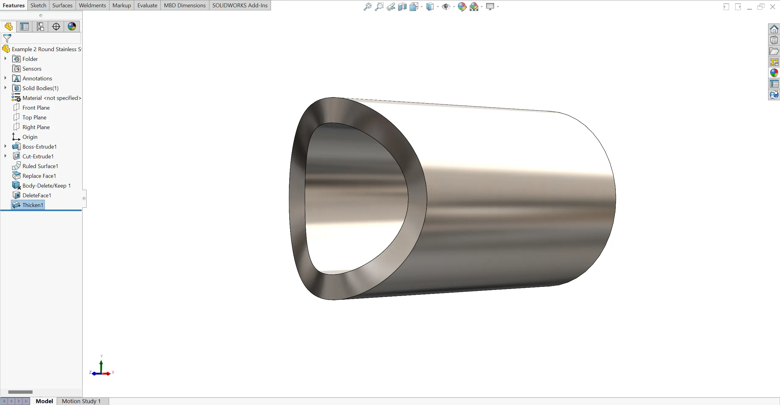
Congratulations! You have successfully normalized the surface of your cut.
Delete Face Method
This method is the quickest way to normalize cuts on round tubing, requiring only two tools. This method can normalize multiple cuts on a round tube at once; however, any mitered cuts will be incorrectly normalized using this method. Be sure to normalize miters separately. Review Designing Normalized Mitered Cuts on Round Tube to learn how to do this.

1. Delete Faces
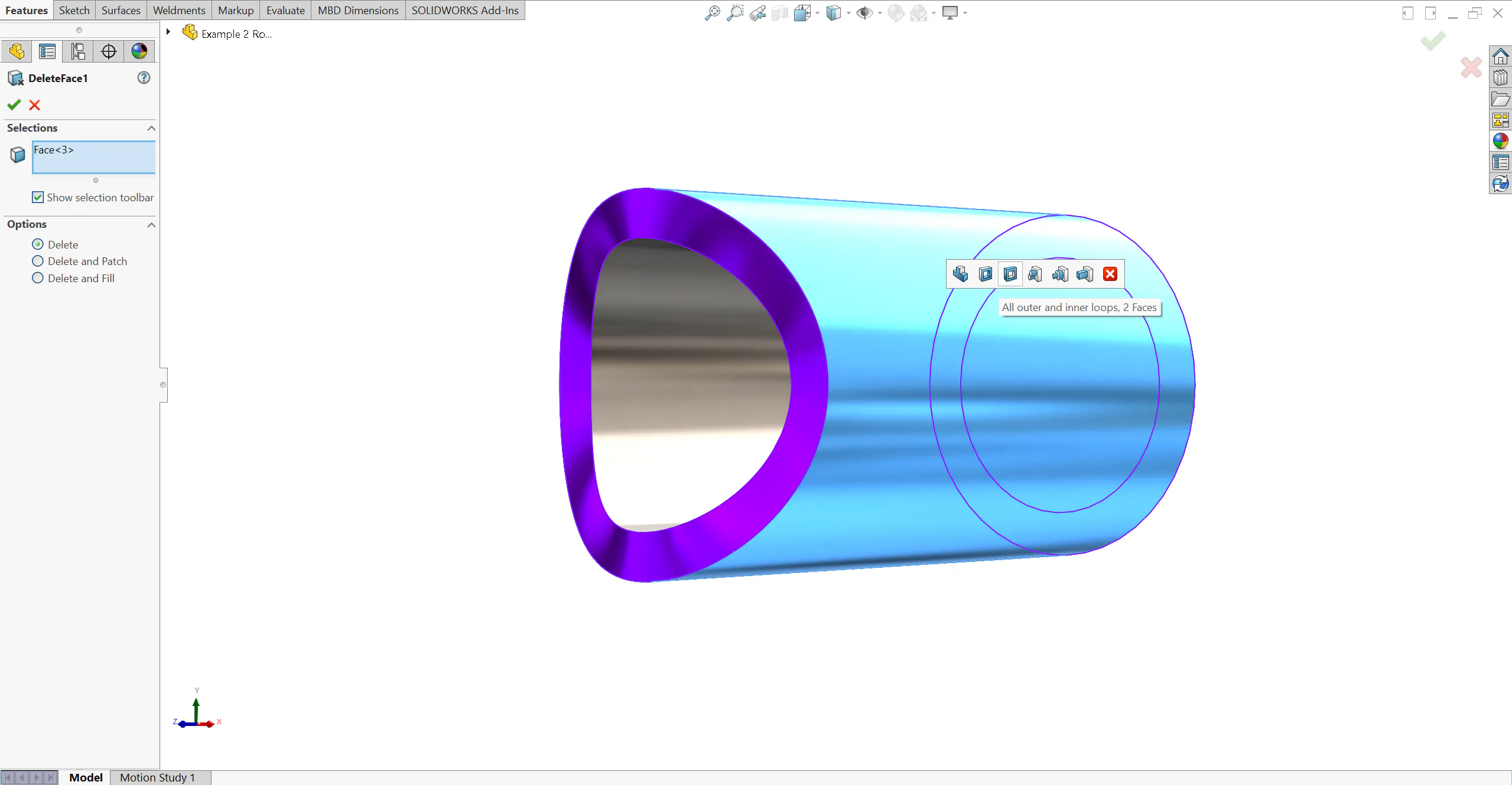
Start by clicking the Delete Face tool in the Surfaces tab. Next, select all faces on your tube EXCEPT the inside face. You can do this by selecting each face individually, or by selecting the outside face and clicking “All Outer and Inner Loops” from the selection toolbar. Check the Options dropdown and click Delete.
Click OK. You should be left with the outside surface of the tube and your ruled surface.
2. Thicken

Now that we have isolated our inside surface, select the Thicken tool in the Surfaces tab. Select the inside tube surface as the Surface to Thicken. Change the thickness direction until the feature is thickening outward. The yellow preview should be outside of your tube.
Enter the wall thickness of your tube and click OK.
Congratulations! You have normalized your tube cuts. This method can normalize multiple cuts at once, saving significant time. It’s important to note that this method works best on straight tubing. Thickening a bent tube will often not result in normal to surface cuts. For visual tips on how to recognize if your cuts are normal to surface, check our gallery here.
FAQ
How Xometry Can Help
Normalizing tube cuts doesn’t have to be daunting or time consuming. We hope these methods help you understand how your round tube cuts will look after fabrication. If you want to make sure you’ve followed these steps correctly, review our gallery here.
Now that your tube cuts are normalized, upload your laser tube cutting projects to our Instant Quoting Engine today!
If you have any feedback about the methods discussed or have methods of your own you’d like to share, email us at support@xometry.com!
Xometry's Tube and Fabrication Services
Laser Tube Cutting Services
High-quality tube laser cutting for metal rectangular, square, and round tubes | Free standard shipping on US and international orders | International prototype pricing includes tariffsTube Bending Services
Xometry offers precision tube bending services for round metal tube stock to meet your needs.Custom Online Weldment Services by Xometry
High-quality custom weldment services available for a variety of materials, manufacturing processes, finishes, and more.