CNC Plasma Cutting Machine


The cleanest cuts you’ve ever seen.


A Computer Numerical Control (CNC) plasma cutting machine refers to a computer controlled thermal cutting system that uses a plasma torch to cut electrically conductive metals (carbon steel, stainless steel, aluminum). A CNC plasma cutting machine performs high-speed 2D profile cutting on sheet and plate, delivering repeatability within ±0.010 in to ±0.030 in across production runs. Fabrication operations apply the process to flat patterns, internal cutouts, and external contours where material thickness ranges from 0.040 in to 6.25 in, depending on power supply capacity between 45 A and 800 A. Core components include a constant current DC power supply, plasma torch with consumables (electrode, nozzle, shield), CNC controller executing G code, servo-driven motion system (X axis, Y axis, Z axis), automatic torch height control, cutting table, gas delivery system operating at 60 psi to 120 psi, and a grounded work lead. Plasma temperatures reach 20,000 °C to 30,000 °C and produce kerf widths from 0.040 in to 0.150 in.
CNC plasma cutting machine supports fabrication of brackets, base plates, gussets, flanges, signage, structural profiles, and machine frames. Construction, heavy equipment manufacturing, shipyard fabrication, and general manufacturing depend on cutting speeds exceeding 60 in per minute on 0.50 in mild steel. Thermal separation distinguishes the process from CNC milling and turning, limiting geometry to planar features. Plasma systems range from $5,000 to $500,000, depending on table size, amperage rating, and motion control precision.
What Is a CNC Plasma Cutting Machine?
A CNC plasma cutting machine operates as a numerically controlled thermal separation system that removes electrically conductive material through arc-constricted plasma energy rather than mechanical chip formation. Electrical power from a constant current DC source establishes a pilot arc inside the torch, and the arc transfers to the grounded workpiece to form the cutting arc once electrical continuity is achieved. Compressed process gas (air, oxygen, nitrogen, argon, hydrogen mixtures) accelerates through a narrow copper nozzle where electrical energy ionizes the gas column into plasma at temperatures reaching 20,000 °C to 30,000 °C. The concentrated plasma stream melts a localized zone of metal, and high velocity gas flow expels molten material to generate a kerf measuring 0.040 in to 0.150 in, depending on amperage from 45 A to 260 A. Integrated CNC motion control drives X-Y axis movement across tables ranging from 4 ft × 8 ft to 10 ft × 40 ft, maintaining positional accuracy within ±0.010 in to ±0.030 in, which defines the industrial capability of a CNC plasma cutting machine.
What Is CNC Plasma Cutting?
CNC plasma cutting is a CNC-controlled thermal cutting process that uses a transferred plasma arc to sever electrically conductive metals. The process establishes an electric arc between the torch electrode and the grounded workpiece, ionizing compressed gas inside a constricted nozzle to generate plasma temperatures of 20,000 °C to 30,000 °C. The high energy plasma jet concentrates thermal input along the programmed cut line, melting localized material, and the high velocity gas stream supplied at 60 psi to 120 psi expels molten metal to produce a kerf ranging from 0.040 in to 0.150 in depending on amperage between 45 A and 260 A. CNC motion control executes G code toolpaths and regulates feed rate, acceleration, and torch height through arc voltage feedback to maintain positional accuracy commonly within ±0.010 in to ±0.030 in. Cutting speeds on 0.50 in mild steel exceed 60 in per minute, supporting high-throughput fabrication of brackets, base plates, and structural profiles, which establishes CNC plasma cutting as a production-grade thermal cutting process.
Is a CNC Plasma Cutting Machine Used for Metal Cutting?
Yes, a CNC plasma cutting machine is used for metal cutting. The process requires an electrically conductive workpiece because the transferred arc completes the electrical circuit through the metal to sustain cutting current. Common materials include carbon steel, stainless steel, and aluminum in sheet or plate form, ranging from 0.040 in up to 6.25 in thickness depending on system amperage between 45 A and 800 A. Fabrication operations apply the process to brackets, base plates, structural profiles, and internal cutouts across table sizes from 4 ft × 8 ft to 10 ft × 40 ft. Cut quality depends on torch height control accuracy within ±0.010 in, consumable wear rate, selected process gas (air, oxygen, nitrogen), and programmed cutting speed matched to material thickness. Industrial production favors the process because cutting speeds on 0.50 in carbon steel can exceed 60 in per minute, and operating cost per foot remains lower than many laser systems at thicknesses above 0.50 in to 0.75 in.
Is CNC Plasma Cutting a Type of CNC Machining?
No, CNC plasma cutting is not CNC machining in the strict manufacturing definition because plasma cutting is a CNC-controlled thermal cutting process rather than a mechanical chip removal process. The process removes material by melting electrically conductive metal with a transferred plasma arc and expelling molten material using a high velocity gas stream supplied at 60 psi to 120 psi. CNC machining refers to processes that remove solid material using a rigid cutting tool (milling, turning, drilling) where shear deformation produces chips and achieves tighter tolerances commonly within ±0.001 in to ±0.005 in. CNC plasma cutting operates under CNC-controlled thermal cutting rather than classical machining, since material separation occurs through localized melting at temperatures reaching 20,000 °C to 30,000 °C. The distinction affects manufacturing planning because plasma cutting produces a heat-affected zone 0.010 in to 0.200 in wide, kerf widths ranging from 0.040 in to 0.150 in, and dimensional tolerances commonly within ±0.010 in to ±0.030 in. Tolerance capability and surface integrity differences clarify the boundary between plasma cutting and CNC Machining.


How does a Plasma Cutter Work?
A plasma cutter works by creating an electric arc that ionizes a gas stream into plasma and directs the plasma through a constricted copper nozzle. The torch electrode carries current, and the workpiece completes the electrical circuit, which creates a transferred arc for cutting. A high-frequency or contact start initiates a pilot arc inside the torch, and the arc transfers to the workpiece once sufficient proximity establishes electrical continuity. Electrical energy density inside the nozzle constriction raises gas temperature to 20,000 °C to 30,000 °C, producing a stable, electrically conductive plasma column rather than heating alone, causing ionization. The plasma jet melts metal along the cut path, and a high velocity gas stream supplied at 60 psi to 120 psi mechanically expels molten material to form a kerf measuring 0.040 in to 0.150 in depending on amperage from 30 A to 800 A. Torch height, cutting current, gas pressure, and travel speed directly influence arc voltage, kerf geometry, dross adhesion, and edge angularity, which explains how does a plasma cutter work through controlled electrical and thermal energy delivery within a plasma cutter system.
How does CNC Plasma Cutting Control the Torch Movement?
CNC plasma cutting controls torch movement through servo motors or stepper motors that drive the X axis and Y axis of the cutting table. A CNC controller interprets G-code motion commands and converts them into coordinated axis movement. The system maintains programmed feed rate, acceleration, and path geometry to follow the toolpath. A torch height control system adjusts the Z axis to maintain consistent arc voltage and standoff distance. Motion control quality affects kerf width consistency, corner accuracy, and dross formation. Accurate motion tuning supports repeatable production patterns.
Does a Plasma Cutter Use Ionized Gas to Cut Metal?
Yes, a plasma cutter uses ionized gas to cut metal. The ionized gas forms plasma, which carries the electric current and produces a high-temperature transferred arc between the electrode and the electrically conductive workpiece. Electrical energy is conducted through a small-diameter nozzle, increasing arc density and raising plasma temperatures to 20,000 °C to 30,000 °C. The high-energy plasma stream concentrates thermal input along a narrow toolpath, causing localized melting of the base material. High velocity gas flow, supplied at 60 psi to 120 psi depending on system rating, mechanically expels molten metal from the kerf rather than relying on heat transfer alone. Kerf width generally ranges from 0.040 in to 0.150 in based on amperage levels between 30 A and 800 A and nozzle diameter selection. The process requires electrically conductive metals because electrical continuity through the workpiece completes the circuit and sustains the cutting arc.
What are the Parts of a CNC Plasma Cutting Machine?
The parts of a CNC Plasma Cutting Machine are listed below.
- CNC Controller: The CNC controller reads the program and commands coordinated motion for the cutting path. The unit manages feed rate, acceleration, and arc start signals. The interfaces with limit switches, motors, torch height control, and Ohmic sensing circuits.
- Plasma Power Supply: The plasma power supply generates the cutting current and voltage needed to maintain the arc. The unit controls the amperage range for different material thicknesses. The unit connects to the torch through high-current leads.
- Plasma Torch: The plasma torch holds the electrode and nozzle and forms the constricted plasma jet. The torch body directs gas flow through the nozzle to stabilize the arc. The torch assembly uses consumables that wear during cutting.
- Torch Height Control System: The torch height control system regulates standoff distance during cutting. The system uses arc voltage sensing to adjust Z axis position. Stable height improves edge quality and reduces consumable wear.
- Motion System (X Axis, Y Axis, Z Axis): The motion system moves the torch across the table. The system uses linear rails, bearings, and drive mechanisms (rack and pinion or ballscrew). Smooth motion improves accuracy and cut consistency.
- Cutting Table and Slats: The cutting table supports the metal sheet during cutting. Slats hold the plate while allowing molten material to fall through. Table design affects part support and cleanup effort.
- Gas Supply and Regulators: The gas supply provides compressed air or process gases for plasma formation. Regulators control pressure and flow rate to match torch requirements. Gas quality affects arc stability and cut quality.
- Ground Clamp and Work Lead: The ground clamp provides the electrical return path for the transferred arc. A stable return connection supports consistent arc ignition. Poor grounding increases arc instability and misfires.
What are the Main Components of a CNC Plasma Cutting System?
The main components of a CNC Plasma Cutting System are listed below.
- CNC Motion Platform: The motion platform moves the torch across the work area using controlled X-axis and Y-axis travel. The platform uses linear guides and a drive system to maintain accuracy. The platform defines the cutting envelope and repeatability.
- Plasma Cutting Source: The cutting source supplies current and voltage for arc ignition and sustained cutting. The source rating determines thickness capability and duty cycle. The source integrates with the CNC for start and fault signals.
- Torch and Consumables: The torch directs plasma through a nozzle to form the cutting jet. Consumables include the electrode, nozzle, swirl ring, and shield cap. Consumable condition strongly affects kerf quality and dross levels.
- Gas and Air Handling: Gas handling delivers compressed air or specialty gases to the torch. Filters and dryers improve gas quality by reducing moisture and oil. Stable gas flow improves arc stability and edge finish.
- Torch Height Control: Torch height control maintains the correct standoff distance above the metal. The system uses voltage feedback or probing to find plate height. Correct height reduces bevel angle and improves cut consistency.
- CAD CAM and G Code Workflow: CAD defines part geometry, and CAM generates toolpaths for the controller. The workflow outputs G code that defines speed, pierce delay, and motion. Program quality affects corner sharpness and cut time.
Does a CNC Plasma Machine Include a Controller and Torch?
Yes, a CNC plasma machine includes a controller and a plasma torch. The controller interprets the cutting program and commands coordinated axis motion across the cutting table. The torch forms a constricted electric arc between the electrode and the workpiece and directs the high-temperature plasma jet into an electrically conductive metal to produce the cut. The controller and torch interface through discrete I O signals, including arc start, arc ok confirmation, and arc voltage feedback for automatic height regulation. Manual plasma systems rely on hand-guided motion without programmed path control or closed-loop height sensing, whereas CNC systems integrate motor drives, motion control software, and voltage-based torch height control to maintain positional accuracy within ±0.010 in to ±0.030 in depending on table design.
Does a CNC Plasma Machine Include a torch? Yes, a CNC plasma machine includes a plasma torch. The torch functions as the cutting head that generates a transferred arc from the electrode to the workpiece and directs a plasma stream with temperatures reaching 20,000 °C to 30,000 °C into the cut zone. The torch connects to a plasma power supply rated from 45 A to 800 A and to a regulated gas system operating in the 60 psi to 120 psi range during cutting. Torch consumables (electrode, nozzle, shield) erode due to thermal loading and electrical wear, influencing kerf width commonly ranging from 0.040 in to 0.150 in. CNC motion control drives the torch along the programmed toolpath, and automatic torch height control maintains arc voltage based standoff distance above the workpiece.
What are the Types of CNC Plasma Cutting Machines?
The types of CNC Plasma Cutting Machines are listed below.
- CNC Plasma Table (Gantry Style): A gantry-style table uses a bridge that moves across the cutting bed. The design supports large sheet sizes and stable motion. The design fits fabrication shops, cutting plate, and sheets.
- CNC Plasma Router Combination Table: A combination table supports plasma cutting and routing on the same platform. The system swaps tools depending on the job type. The design supports mixed material workflows, yet setup complexity increases.
- Industrial High Definition Plasma System: A high definition system uses advanced torch technology and tighter arc constriction. The design improves edge angularity and cut surface finish compared to conventional plasma. The design fits production cutting environments.
- CNC Plasma Pipe and Tube Cutter: A pipe cutter uses rotary axes to cut round tube and pipe profiles. The system supports saddles, copes, and bevels for welding prep. The system fits structural fabrication and piping work.
- Portable CNC Plasma Cutting System: A portable CNC system uses a smaller table or track-mounted motion system. The system fits jobsite cutting and repair work. The system trades cutting envelope size for mobility.
What is the Difference Between CNC Plasma Cutter and Plasma Cutter Machine?
The difference between a CNC plasma cutter and a plasma cutter machine is CNC plasma cutter describes a CNC-controlled system that moves the torch along a programmed toolpath, while a plasma cutter machine is a broader term that can refer to either a CNC table system or a manual handheld plasma cutter. CNC plasma cutting uses motors, a CNC controller, and a cutting table to produce consistent motion and repeatable part geometry. Manual plasma cutting relies on operator hand control, which increases variation in travel speed, torch angle, and cut path accuracy. CNC systems support nesting, automated production, and repeatable batches for fabrication work. Manual plasma cutters fit repair work, jobsite cutting, and quick trimming tasks where tight dimensional control is not required. The distinction affects tolerance expectations, repeatability, and production.
Are CNC Plasma Cutters More Accurate Than Manual Plasma Cutters?
Yes, CNC plasma cutters are more accurate than manual plasma cutters. CNC motion control follows programmed toolpaths with consistent speed and direction. Manual cutting depends on operator steadiness, which affects kerf width consistency and edge straightness. CNC cutting improves repeatability across multiple parts in a batch. Accuracy depends on machine rigidity, torch height control, and consumable wear. Tight tolerance work require secondary machining after plasma cutting.
What is the Working Principle of CNC Plasma Cutting?
The working principle of CNC plasma cutting centers on electrical arc constriction and controlled thermal energy delivery to electrically conductive materials. A constant current DC power source establishes a pilot arc inside the torch between the electrode and nozzle, and the arc transfers to the grounded workpiece once proximity permits arc attachment. Compressed process gas (air, oxygen, nitrogen, argon, hydrogen mixtures) passes through a constricted copper nozzle where electrical energy ionizes the gas column into plasma at temperatures of 20,000 °C to 30,000 °C. The high-energy-density plasma stream melts localized material along the programmed toolpath, and the high-velocity gas stream mechanically expels molten metal from the cut zone. Kerf width depends on nozzle diameter, amperage level, and arc constriction design, with typical production ranges from 0.040 in to 0.150 in across 45 A to 800 A systems. CNC motion control regulates feed rate, acceleration, and pierce delay relative to plate thickness, and automatic torch height control maintains arc voltage based on standoff to stabilize cut geometry.
How does CNC Programming Control Plasma Cutting Operations?
CNC programming controls plasma cutting operations by converting CAD geometry into CAM-generated toolpaths and CNC code that defines torch motion, feed rate, pierce delay, and cut sequencing. CAD defines the part outline, while CAM software applies kerf compensation, lead-ins, lead-outs, and nesting layouts to reduce scrap and improve material yield. The CNC controller reads the program and commands coordinated axis motion across the cutting table through servo or stepper motor control. Programmed cutting speed and torch height targets influence dross formation, bevel angle, and edge finish. Pierce height and pierce delay settings reduce tip damage and improve cut starts on thicker plate. Proper programming improves repeatability and reduces rework, which aligns with CNC programming principles for production.
Does CNC Plasma Cutting use G Code for Programming?
Yes, CNC plasma cutting uses G code for programming. G code defines axis motion, feed rate, and path geometry for the torch toolpath. Plasma cutting functions use controller commands for torch on and torch off control, pierce delay timing, and torch height control routines, with implementation handled through M codes or controller-specific macros. CAM software generates G code after converting CAD geometry into machine toolpaths and applying cut parameters. Controller brands use different G-code dialects and different M code assignments, yet the overall programming structure remains based on standard motion commands, which aligns with G-Code: Definition, Function, and Different Types.
What are Plasma Cutter Settings?
Plasma cutter settings are adjustable process parameters that control arc energy, gas flow, and torch movement to match metal thickness and desired cut quality. Key settings include cutting current, arc voltage, gas pressure, pierce height, cut height, and cutting speed. Higher current increases heat input and supports thicker metal cutting, while lower current fits thin sheet to reduce warping. Gas pressure affects arc constriction and molten metal removal from the kerf. Incorrect settings create dross, excessive bevel, wider kerf, or incomplete penetration. Consistent settings improve edge finish and consumable life.
How do Plasma Cutting Settings Affect Cut Quality?
Plasma cutting settings affect cut quality by controlling arc stability, kerf width, bevel angle, dross formation, and surface finish. Cutting speed controls the amount of heat input per unit length. Excessively slow speed increases dross and widens the kerf, while excessively fast speed causes incomplete penetration and heavy drag lines. Torch height affects arc focus and edge angularity. Gas pressure influences arc constriction and molten metal ejection. Current level controls maximum thickness capability and affects cut-edge smoothness. Balanced parameter selection improves repeatability across production runs.
Does Metal Thickness Require Different Plasma Cutter Settings?
Yes, metal thickness requires different plasma cutter settings. Thicker metal requires higher cutting current and slower cutting speed to maintain full kerf penetration and stable arc performance. Thin sheet requires lower current and controlled travel speed matched to amperage to maintain arc stability, minimize top edge rounding, limit heat-affected zone width, and reduce dross adhesion. Pierce delay increases as thickness increases to allow the arc column to fully penetrate before X-Y motion begins, with delays ranging from 0.20 s for a 0.125 in sheet to 4.0 s or more for thick plate. Torch height targets change by thickness and torch design to maintain correct arc standoff, with typical cut heights between 0.060 in and 0.150 in depending on nozzle type and amperage. The manufacturer's cut charts list recommended amperage (45 A to 800 A), gas pressure (60 psi to 120 psi), pierce height, cut height, and speed for each material and thickness, which aligns with the fundamentals described in metal definition.


What are the Uses of CNC Plasma Cutting Machines?
The uses of CNC plasma cutting machines are cutting 2D profiles from electrically conductive sheet and plate for fabrication, manufacturing, and construction work. CNC plasma cutting machines produce brackets, base plates, gussets, flanges, signage panels, and structural profiles used in welded assemblies and metal frameworks. The process supports nesting to reduce scrap and increase throughput on standard sheet sizes. Fabrication shops use CNC plasma cutting for fast production of flat parts that require contour cutting rather than tight tolerance machining. Industrial operations use CNC plasma cutting for thicker plate processing, where cutting speed and equipment cost provide advantages over many laser systems. CNC plasma cutting supports prototype parts and batch production because toolpaths are changed through programming rather than physical tooling changes.
The efficiency of CNC plasma lies in the balance between arc voltage stability and travel speed (especially on thicker sections). While fiber lasers dominate the thin-gauge precision market, plasma remains the workhorse for heavy industrial plate where the cost per foot and throughput are the primary drivers for a fabrication shop.


Where is CNC Plasma Cutting Used in Fabrication and Manufacturing?
CNC plasma cutting is used in fabrication shops and manufacturing facilities that process sheet and plate for structural and mechanical parts. Fabrication operations use the process to cut steel components for frames, brackets, and welded assemblies. Manufacturing plants use the process to produce parts for equipment housings, machine bases, and structural supports. Heavy industry uses CNC plasma for large plate processing in construction, mining equipment, and industrial repair. The process fits environments that require fast cutting and flexible part geometry. Production efficiency increases through nesting and repeatable toolpaths.
Is CNC Plasma Cutting Used in Industrial Metal Cutting?
Yes, CNC plasma cutting is used in industrial metal cutting. CNC plasma cutting supports high throughput cutting of electrically conductive plate (carbon steel, stainless steel, aluminum) on large format tables in the 4 feet (ft) × 8 ft to 10 ft × 40 ft range. Industrial applications include structural steel fabrication, heavy equipment manufacturing, and shipyard plate processing. Plasma cutting maintains a cost advantage versus fiber laser for very thick plates, with the strongest economic break point commonly occurring above 1.00 in to 1.25 in thickness, depending on material grade, required edge quality, and consumable costs. Cut quality remains sufficient for welding and general fabrication, with typical kerf widths around 0.060 in to 0.120 in and edge angularity that increases as thickness rises. Secondary operations (grinding, machining) address tighter tolerance requirements, including holes requiring ±0.010 in to ±0.020 in positional control or critical bore roundness.
How does CNC Plasma Cutting Compare to Other CNC Machines?
The CNC plasma Cutting compare to other CNC machines by using thermal energy from a plasma arc to cut electrically conductive sheet and plate, while CNC milling and CNC turning remove material through mechanical chip cutting. CNC plasma cutting focuses on 2D profiling, internal cutouts, and fast production of flat parts, which makes the process common in fabrication shops and structural steel work. CNC milling and CNC turning produce tighter tolerances, smoother surfaces, and true 3D geometry (pockets, bores, threads, complex contours). CNC plasma cutting produces a heat-affected zone and a wider kerf, which reduces dimensional accuracy compared with machining operations. CNC laser cutting provides a smaller kerf width and cleaner edges on thin sheet, while plasma cutting performs better on thicker plate at lower equipment cost. CNC plasma cutting fits high-speed profile cutting, while other CNC machines fit precision part manufacturing.
How is CNC Plasma Different from CNC Milling and CNC Turning?
CNC plasma is different from CNC milling and CNC turning because plasma uses a high-temperature ionized gas arc to sever conductive sheet, while milling and turning use mechanical cutting with rotating tools. CNC plasma is used for 2D profile cutting on plate and sheet, including external contours and internal cutouts. CNC milling produces 3D geometry, pockets, drilled holes, and tight tolerance features from solid stock. CNC turning produces axisymmetric parts from bar or tube stock, including shafts, bores, grooves, and threads. Plasma cutting creates a heat-affected zone and dross that may require secondary cleanup. Milling and turning produce machined surfaces without thermal cutting effects. Process selection depends on part geometry, tolerance requirements, edge quality, and production quantity.

Is CNC Plasma Cutting More Cost-Effective Than CNC Laser?
Yes, CNC plasma cutting is more cost-effective than CNC laser for metal cutting jobs on thicker carbon steel plates. Plasma equipment costs less than fiber laser systems in comparable cutting envelope sizes. Operating costs remain lower because plasma systems rely on consumables and compressed air or gas rather than high-power laser sources. Laser cutting provides tighter tolerances, smaller kerf width, and cleaner edges on thin sheet. Plasma cutting remains a strong choice for fabrication work where speed and cost matter more than laser-level precision.
How is CNC Plasma Cutting Different from a Drilling Machine?
The CNC Plasma Cutting is different from a drilling machine by using a plasma arc and high velocity gas to melt and eject metal along a programmed cut path, while drilling removes material by cutting chips with a rotating drill bit. Plasma cutting is a thermal cutting process that produces kerfs for external profiles, internal cutouts, and slot geometry on electrically conductive sheet and plate. Drilling is a mechanical machining process that produces round holes with controlled diameter and controlled depth for fasteners and precision features. Plasma cutting prioritizes cutting speed and profile flexibility, while drilling prioritizes dimensional accuracy and hole quality. Fabrication workflows pair plasma cutting for part outlines and drilling for precision hole operations (reaming, tapping, countersinking), which aligns with the machining fundamentals described in the drilling machine.
Is Plasma Cutting Used for Profile Cutting?
Yes, plasma cutting is used for profile cutting. CNC motion control guides the plasma torch along programmed contours to cut external profiles and internal features. The process is used for brackets, base plates, gussets, signage, and structural parts made from electrically conductive metals (carbon steel, stainless steel, aluminum). Profile cutting works best on sheet and plate, where 2D geometry defines the part shape. Cut accuracy depends on machine rigidity, motion calibration, torch height control, consumable condition, and cutting parameters (amperage, speed, gas pressure). CNC programming improves repeatability for nested production runs and consistent part geometry.
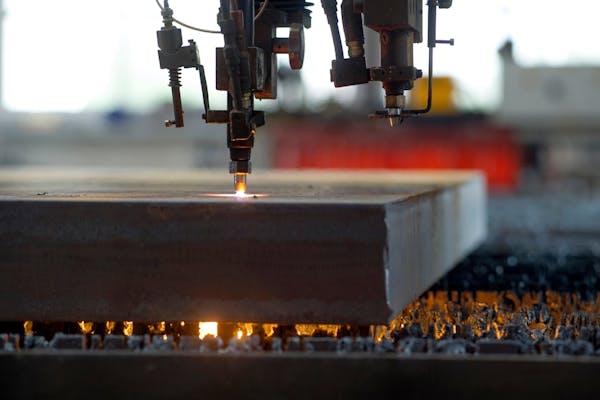
Flame cutting thick-gauge steel.
Image Credit: Shutterstock.com/fotomarc
How Xometry Can Help
To learn more about CNC plasma cutting, or any other type of cutting, reach out to one of our Xometry representatives who would be happy to help. You can also choose from our wide range of manufacturing services, like CNC machining, 3D printing, and laser cutting. To get started, you can request a free no-obligation quote today.
Disclaimer
The content appearing on this webpage is for informational purposes only. Xometry makes no representation or warranty of any kind, be it expressed or implied, as to the accuracy, completeness, or validity of the information. Any performance parameters, geometric tolerances, specific design features, quality and types of materials, or processes should not be inferred to represent what will be delivered by third-party suppliers or manufacturers through Xometry’s network. Buyers seeking quotes for parts are responsible for defining the specific requirements for those parts. Please refer to our terms and conditions for more information.